Wide
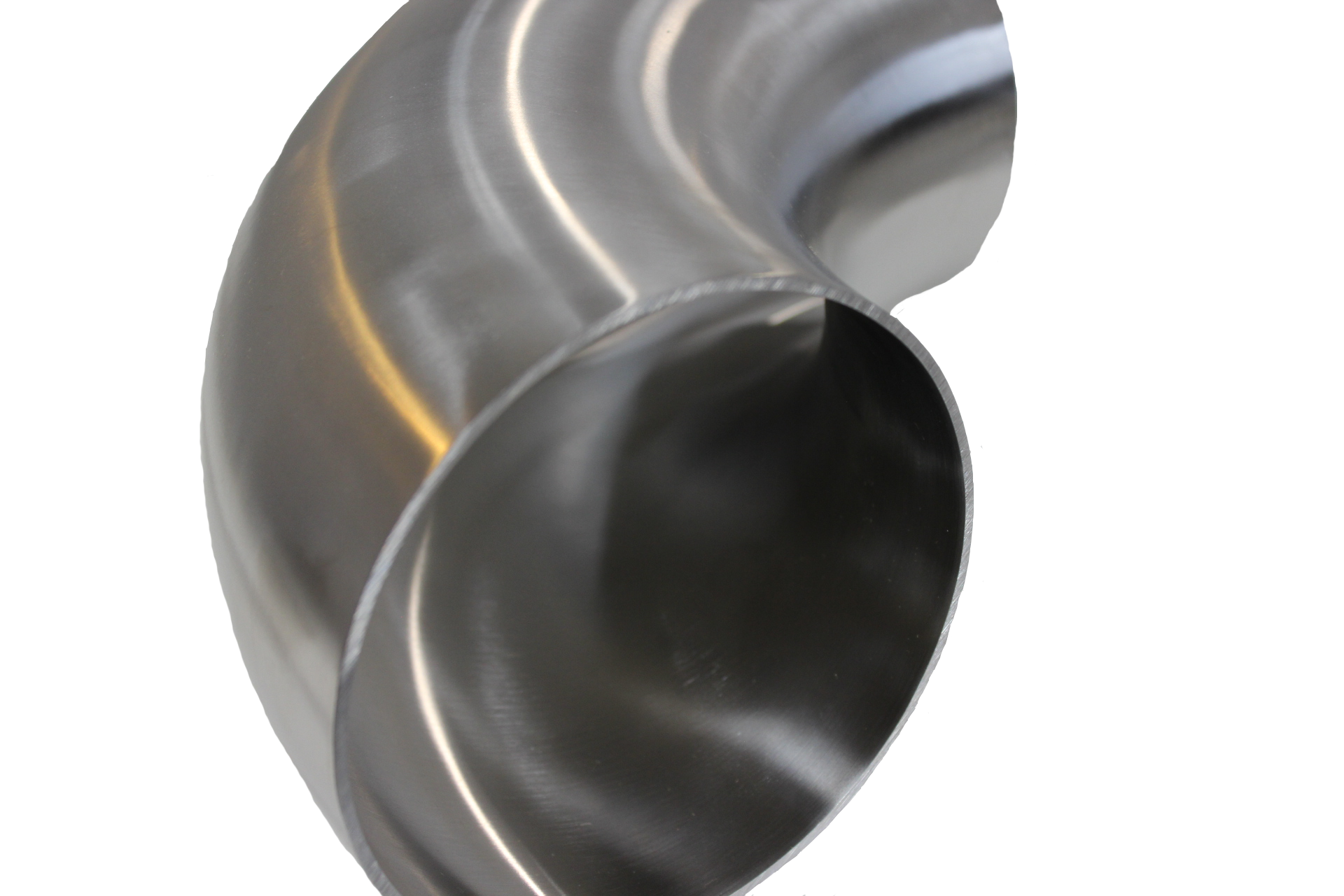
Large-diameter, thick-walled metallic pipe elbows, central method in
top-pressure piping platforms for oil, fuel, or petrochemical packages, face
authentic challenges at some point of fabrication on account of the induction scorching bending job.These elbows, ordinarily conforming to ASME B31.three (Process Piping) or ASME B16.nine
specifications, need to shield structural integrity under internal pressures up to 15MPa and temperatures from -29°C to four hundred°C, when resisting corrosion, fatigue,
and creep. The induction bending task, which heats a localized band to850-1100°C to let plastic deformation, inherently thins the outer wall
(extrados) via tensile stretching, most likely compromising electricity andpressure containment. Controlling this thinning—generally 10-20% of nominal wall
thickness—and verifying that tension concentrations inside the thinned area complywith ASME B31.three specs call for a synergy of properly task keep an eye on and
finite element prognosis (FEA). This technique now not simply guarantees dimensionalcompliance yet additionally safeguards against burst, collapse, or fatigue disasters in
carrier. Below, we discover the mechanisms of thinning, approaches for itsmanagement, and FEA-driven verification of force, with insights from Pipeun’s
skills in prime-performance tubulars.
Mechanisms of Wall Thinning in Induction Hot Bending
Induction hot bending, generally used for forming elbows (e.g., 24” OD, 25-50 mm
wall thickness, API 5L X65/X70), employs a excessive-frequency induction coil (10-50
kHz) to heat a slim pipe section to the austenitic number (900-a thousand°C forcarbon steels), followed by way of managed bending round a pivot arm (bend radius
1.5D-3D, D=pipe diameter). The extrados undergoes tensile hoop strain(ε_h~5-15%), elongating the outer fiber and thinning the wall, whilst the
intrados compresses, thickening slightly. Thinning, Δt/t_n (t_n=nominalthickness), follows the geometry of deformation: Δt/t_n ≈ R_b / (R_b + r_o),
in which R_b is bend radius and r_o is pipe outer radius, predicting 10-15%thinning for a 3-d bend (R_b=3-D). For a 24” OD pipe (r_o=304.eight mm, t_n=30 mm, R_b=1828.eight
mm), theoretical thinning is ~14.three%, slicing t to ~25.7 mm on the extrados.
Mechanistically, thinning is pushed by way of plastic drift: at 950°C, the steel’s yield
force (σ_y) drops to ~50-a hundred MPa (from 450 MPa at RT for X65), enabling
tensile elongation but risking necking if pressure prices (ė~zero.01-0.1 s^-1) exceedgo with the flow localization thresholds. Residual stresses put up-cooling (σ_res~one hundred-two hundred MPa,
tensile at extrados) and microstructural shifts (e.g., ferrite coarsening in HAZ)expand tension concentrations, with stress concentration explanations (SCF,
K_t~1.2-1.five) at the extrados raising local stresses to one.5x nominal belowtension. ASME B31.three mandates that thinned regions take care of strain integrity
(hoop stress σ_h = PD/(2t) < allowable S_h, aas a rule 2/three σ_y), with t_min ≥ t_n- tolerances (e.g., 12.5% in step with API 5L), guaranteeing no burst or fatigue failure
lower than cyclic rather a lot.
Controlling Thinning in Induction Hot Bending
Precise management of extrados thinning hinges on optimizing approach
parameters—temperature, bending pace, cooling price, and tooling—to diminish
stress localization while making certain dimensional constancy. Pipeun’s inductionbending protocol, aligned with ISO 15590-1 and ASME B16.forty nine, integrates real-time
tracking and suggestions to cap thinning at 10-15% for significant-diameter elbows (DNsix hundred-1200, t_n=20-50 mm).
1. **Temperature Control**: Uniform heating to 900-950°C (inside of ±10°C) because of
induction coils minimizes movement rigidity gradients, slicing necking. Overheating(>one thousand°C) coarsens grains (ASTM 6-eight → 4-6), decreasing ductility and risking >20%
thinning; underheating (<850°C) elevates σ_y, inflicting springback and cracking. <p> Infrared pyrometers and thermocouples embedded in trial sections feed PID controllers, adjusting coil persistent (50-one hundred kW) to sustain a 50-75 mm heat band,ensuring ε_h uniformity across the extrados. For X65, 950°C optimizes
Zener-Hollomon parameter (Z = ė exp(Q/RT), Q~280 kJ/mol), balancing pressure costand recrystallization to reduce Δt.
2. **Bending Speed and Strain Rate**: Bending at 10-30 mm/min (ė~zero.01 s^-1)
prevents localized thinning by means of permitting dynamic restoration in ferrite, according toconstitutive types σ = K ε^n ė^m (n~0.2, m~0.05 at 950°C). Faster speeds (>50
mm/min) spike ε_h to twenty%, thinning t via 18-22%; slower speeds (<5 mm/min) <p> lengthen heating, coarsening microstructure. Servo-controlled pivot arms synchronize with pipe strengthen, affirming R_b fidelity (±1%) by laserprofilometry.
3. **Cooling Rate and Post-Bend Treatment**: Controlled air or water-mist
cooling (five-10°C/s) post-bending prevents martensite formation (Ms~350°C for X65)whilst relieving σ_res as a result of recovery. Normalizing (900°C, 1 h/inch, air cool)
post-bend refines grains to ASTM 8-10, chopping SCF through 10-15% and restoringt_min integrity. Over-quenching risks onerous phases (HRC>22), raising crack
susceptibility.
4. **Tooling and Pipe Selection**: Thicker establishing walls (t_n + 10-15%)
compensate for thinning, making certain t_min ≥ ASME B31.3 standards. Induction
coils with tapered profiles distribute warm, narrowing the HAZ (20-30 mm), at the same time www.avatur.com asmandrel-loose bending for large radii avoids inner buckling. API 5L X70 pipes
with low CE (
In perform, Pipeun’s 2025 campaign for 36” OD, forty mm wall X70 elbows finished
Δt=12% (t_min=35.2 mm) at R_b=3-d, proven by way of ultrasonic thickness gauging (ASTM
E797, ±zero.1 mm), with <5% variance across batches, assembly B16.9 tolerances.<p>
FEA Verification of Stress Concentration and Strength Compliance
FEA, in step with ASME VIII Div 2 or B31.three, verifies that thinned extrados areas
resist design pressures and cyclic quite a bit without exceeding allowable stresses
or starting up fatigue cracks. Using equipment like ANSYS or ABAQUS, Pipeun itemselbows as 3-d shell elements (S8R, ~10^5 nodes) to trap tension fields,
incorporating drapery, geometric, and loading nuances.
1. **Model Setup**:
- **Geometry**: A 24” OD, 25.7 mm t_min (post-thinning) elbow, R_b=three-D, ninety° bend,
meshed with quadratic resources (0.5 mm at extrados). Thinning is mapped from UTfiles, with t varying parabolically along the arc (t_max at intrados~30 mm).
- **Material**: API 5L X65 (E=two hundred GPa, ν=0.three, σ_y=450 MPa, UTS=550 MPa), with
elasto-plastic conduct by Ramberg-Osgood (n=10). Welds (if gift) use HAZ
properties (σ_y~400 MPa, per ASME IX quals).
- **Loads**: Internal rigidity P=10 MPa (σ_h = PD/(2t) ~95 MPa), bending moments
(M_b=10^5 Nm from wave hundreds), and residual stresses (σ_res=a hundred and fifty MPa tensile,from hollow-drilling documents).
- **Boundary Conditions**: Fixed ends simulating flange constraints, with cyclic
loading (Δσ=50-one hundred MPa, R=0.1) for fatigue.
2. **Stress Analysis**:
FEA computes von Mises stresses (σ_e = √[(σ_h - σ_a)^2 + (σ_a - σ_r)^2 + (σ_r -
σ_h)^2]/√2), settling on height σ_e~200-250 MPa at the extrados mid-arc, with
K_t~1.three because of the curvature and thinning. ASME B31.3 makes it possible for σ_e ≤ S_h = 2/3 σ_y(~three hundred MPa for X65 at one hundred°C), with t_min gratifying t_m = P D_o / (2S_h + P) + A
(A=corrosion allowance, 1 mm), yielding t_m~22 mm—met by way of t_min=25.7 mm, ensuringdrive integrity. Stress linearization (ASME VIII) separates membrane (σ_m~ninety
MPa) and bending stresses (σ_b~one hundred MPa), confirming σ_m + σ_b < 1.5S_h (~450MPa).
three. **Fatigue Assessment**:
Fatigue lifestyles is estimated through S-N curves (DNVGL-RP-C203, F1 curve for welds) and
LEFM for crack progress. For Δσ=one hundred MPa, S-N yields N_f~10^6 cycles, however FEA
refines local Δσ_local = K_t Δσ~one hundred thirty MPa at extrados, decreasing N_i~4x10^five cycles.Paris’ regulation (da/dN = C ΔK^m, C=10^-12 m/cycle, m=3.five) fashions propagation from
an preliminary flaw a_0=0.2 mm (NDT reduce, PAUT), with ΔK = Y σ √(πa) (Y~1.2 forsemi-elliptical surface cracks). Integration offers N_p~2x10^5 cycles to a_c=20
mm (K_c~100 MPa√m), totaling N_f~6x10^5 cycles, exceeding layout existence (10^fivecycles for 20 years at 0.1 Hz). Seawater CP outcomes are factored due to m=4,
making certain conservatism.
four. **Validation**:
FEA effects are pass-checked with burst checks (ASME B31.3, 1.5x layout
pressure) and full-scale fatigue rigs (ISO 13628-7), with <8% deviation in σ_e <p> and 10% in N_f for X65 elbows. UT and RT (ASME V) ascertain no defects submit-bend, whilst SEM fractography verifies ductile failure modes (dimples vs. cleavage) atthinned zones. A 2024 North Sea project confirmed Pipeun’s 36” elbows, with
t_min=35 mm passing 12 MPa hydrostatics and 10^6-cycle fatigue, aligning withFEA predictions.
Strength Compensation Strategies
To offset thinning, Pipeun employs:
- **Oversized Blanks**: Starting with t_n+15% (e.g., 34.5 mm for 30 mm objective)
guarantees t_min>22 mm publish-thinning, consistent with B31.three.
- **Post-Bend Normalizing**: At 900°C, restores microstructure, cutting σ_res
via 60% and K_t to ~1.1, boosting fatigue lifestyles 20%.
- **Localized Reinforcement**: Extrados cladding (e.g., Inconel as a result of GTAW) or
thicker segments in excessive-rigidity zones, proven with the aid of FEA to cap σ_e<280 MPa.</p>
Challenges embrace HAZ softening (HRC drop to 18), mitigated by way of low CE (<0.38) </p>alloys, and thermal gradients, addressed via multi-coil induction for ±five°C
uniformity. Emerging AI-driven FEA optimizes bending parameters in true-time,
predicting Δt within 2%, while laser scanning put up-bend refines t_min accuracy.
In sum, Pipeun’s mastery of induction bending—by the use of thermal precision, controlled
pressure, and FEA-tested potential—ensures great-diameter elbows defy thinning’s
perils, assembly ASME B31.3 with tough margins. These conduits, engineered toundergo, stand as Steel Pile pipe silent sentinels within the pressure vessel pantheon.